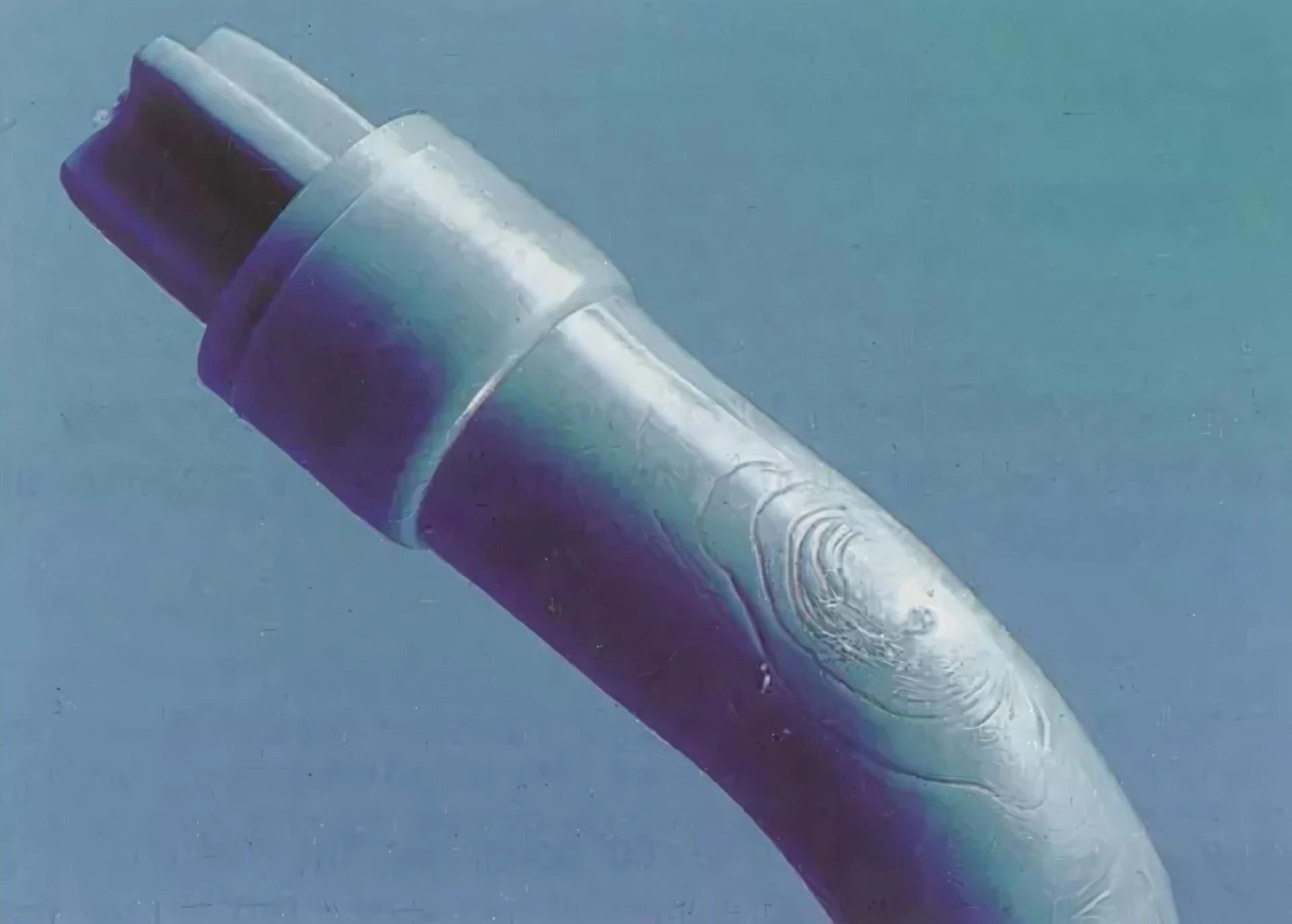
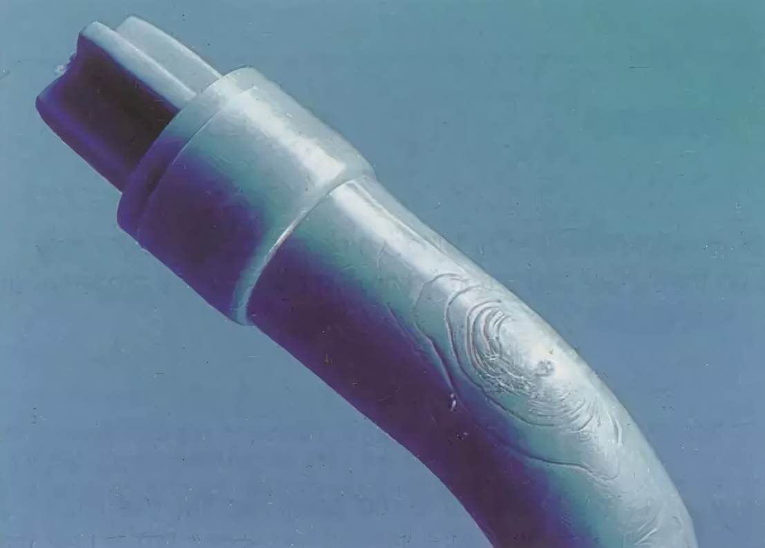
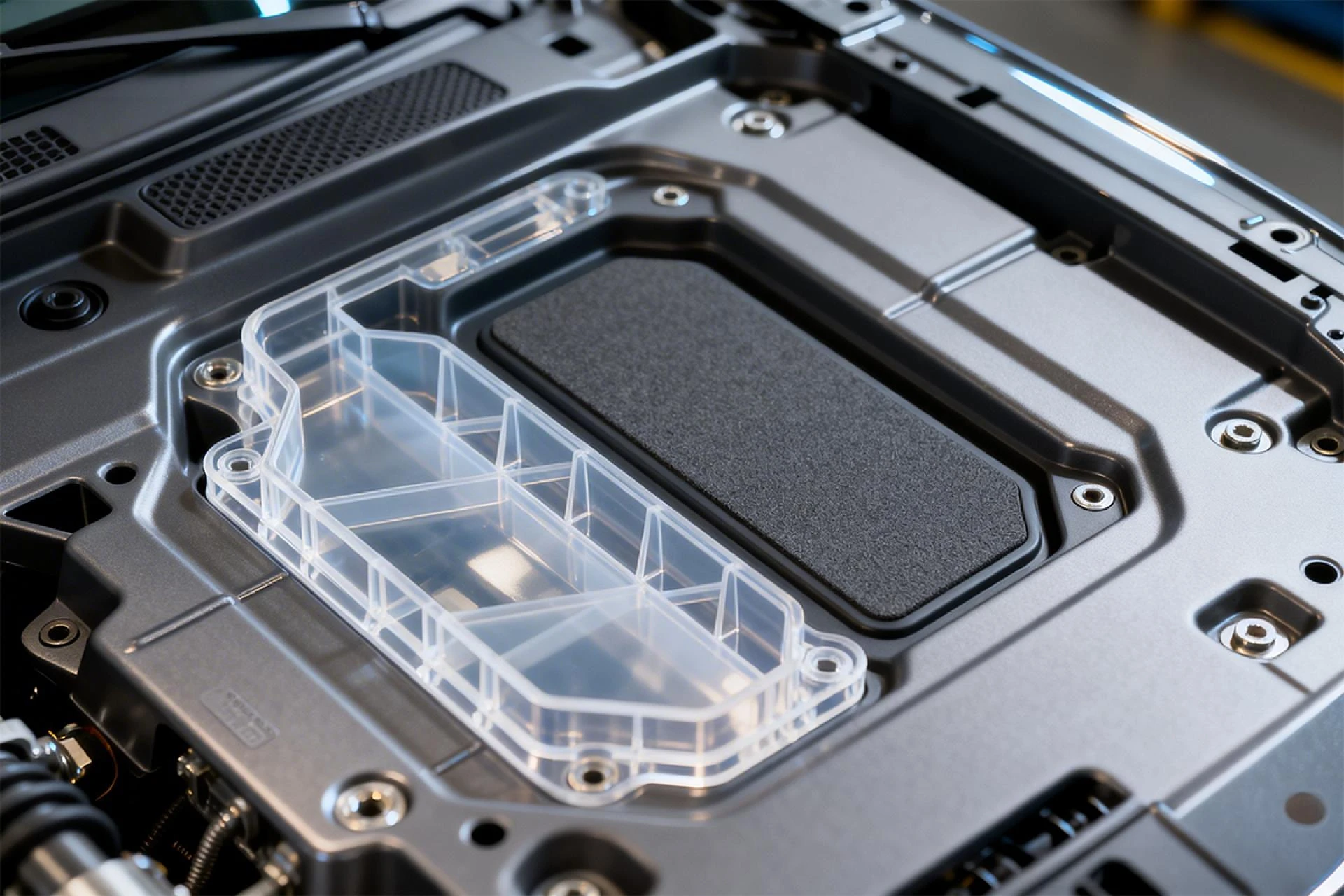
During the mass production of air conditioner panels of a home appliance company last year, we found that grayish-colored streaks frequently appeared in the gate area. These streaks appeared as a grayish-colored melt stream ejected from the gate during injection molding service, and when it slightly touched the mold wall, it was immediately covered by the subsequent melt package. To make matters worse, 30% of these defects were completely hidden inside the product and did not show up as fine cracks until the coating process, resulting in the scrapping of the entire batch. This case reveals the hidden and destructive nature of the flow line - it not only affects the appearance, but also triggers deep quality risks.
An in-depth analysis of the formation mechanism of radial lines
The nature of radial lines is a combination of uncontrolled melt flow and thermodynamic imbalance. When the melt enters the mold cavity through the gate, if the front end of the fluid suddenly loses propulsion power, it will form a flow stagnation zone in the large mold cavity. At this point, the high-temperature melt that enters first contacts the low-temperature mold wall (usually with a temperature difference of more than 50°C) and rapidly cools and solidifies, failing to fully integrate with the subsequent melt. This discontinuous flow will trigger a triple chain reaction:
First, the surface melt produces tensile stresses due to rapid freezing; second, the flow interruption leads to abnormal molecular chain orientation; and finally, a fragile interface is formed that contains cold strain zones and residual stresses. Experimental data show that such structural defects can make the product impact strength decreased by more than 35%.
Precise regulation strategy of process parameters
It is difficult to cure flow lines simply by relying on experience to regulate the machine, and a scientific parameter system must be established. Injection speed is the first control element: too fast speed will make the melt ejected like a bullet, forming a separate melt stream. We adopt a three-stage injection strategy of slow-fast-slow, reducing the speed to 40% of the standard value at the gate breakthrough stage, and then increasing the speed after the melt is smoothly spread. At the same time, temperature management needs to be zoned and refined:
Heat up the barrel metering section by 15°C (except for heat-sensitive materials such as PC)
The mold temperature in the gate area needs to be more than 20℃ higher than other areas
Increase screw back pressure to 8-12MPa to enhance plasticizing uniformity.
The following table summarizes the optimization logic of key process parameters:
| Defect Cause | Optimization Plan | Action Mechanism |
|---|---|---|
| Excessive injection speed | 40% speed reduction at gate + multi-stage control | Eliminate melt jetting phenomenon |
| Insufficient melt temperature | Targeted heating in metering section (ΔT≤15℃) | Reduce melt viscosity to promote fusion |
| Unbalanced mold temperature | Local heating at gate (ΔT≥20℃) | Delay surface curing time |
| Poor plasticization uniformity | Back pressure increased to 8-12MPa | Reduce melt density fluctuation |
Fundamental Improvements in Mould Design
Process adjustments can only alleviate the symptoms, gate structure optimization is the cure. We implemented three key improvements in the air conditioner panel project:
Elimination of sharp transition: the 90° right angle between the gate and the mold wall was changed to an R1.5mm arc to make the melt turn smoothly.
Enlargement of the gate size: The gate cross-sectional area was increased by 40% and the flow rate was reduced from 12m/s to 7m/s.
Repositioning of the gate: offsetting the center gate to the side wall and placing a barrier post 8mm in front of it
One of the most effective of these is the barrier injection technique - a diffusion flow formed by a precision-calculated aluminum alloy baffle that forces the initial melt to impact. This laminar flow front completely eliminates flow lines and has minimal impact on the product structure. After the improvement, the defect rate of air-conditioning panel was reduced from 15% to 0.3%, which verifies the industry guideline of "seven parts mold, three parts process".
The implementation path of the system solution
The eradication of flow lines requires the synergistic optimization of the process and the mold:
The first stage of parameter debugging: using multi-stage injection with local temperature rise, the defects are controlled within an acceptable range in the short term.
The second stage is the implementation of the mold modification: focusing on the optimization of the gate geometry, in which the modification of the arc transition can be completed in only 4 hours.
Ultimate solution: Barrier injection + fan gate combination was used in the new mold design to prevent defects from the source.
It should be especially emphasized that for special working conditions such as glass fiber reinforced materials, it is also necessary to add a mold thermostat to achieve dynamic temperature control. An automotive parts company not only eliminates flow lines, but also improves the fatigue life of the product by more than 2 times through this system solution.
Core Conclusions and Technical Alerts
The solution of flow lines proves the truth that the essence of injection molding defects is energy management. Perfect molding can only be achieved by controlling the transfer efficiency of melt kinetic energy (speed), thermal energy (temperature) and potential energy (pressure). This requires the engineer to:
- Understand the shear heat generation mechanism of the melt at the gate
- Master the principle of heat transfer equilibrium in the mold cavity
- Establish the correlation model between process parameters and mold structure
Last but not least: when encountering thick-walled parts with center gate structure, please directly adopt barrier injection technology to avoid unnecessary process debugging - this is our valuable experience from 37 failed cases.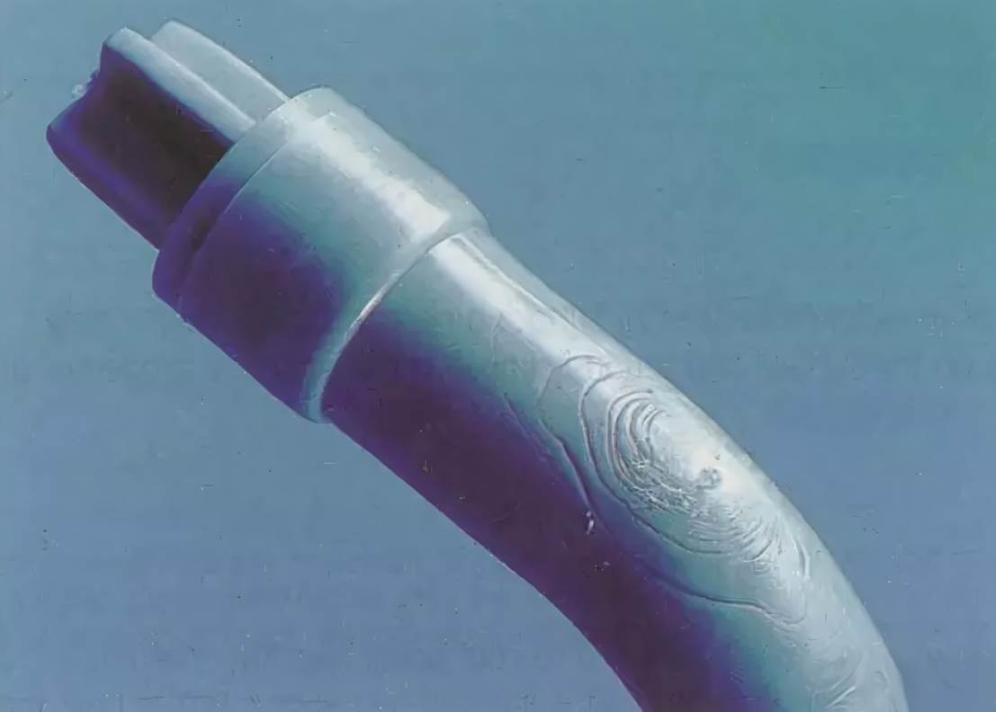


Sign in to leave a comment.