A dual power supply is a type of power source that provides both positive and negative voltages with a common ground. This type of power supply is widely used in circuits such as operational amplifiers (op-amps), audio amplifiers, and other electronic devices that require both voltages to function properly.
In this article, we will explain the dual power supply circuit diagram in simple terms with explanations and also answer an important question: How does a dual power supply work?
What is a dual power supply?
A dual power supply is different from a regular power supply because it provides:
- +V (positive voltage output)
- -V (negative voltage output)
- 0V (ground or common point)
This is useful for circuits that require a balanced power source instead of just a single voltage. Many electronic circuits, especially op-amp-based systems, require both positive and negative voltages to function properly.
For example, an audio amplifier requires +12V and -12V to function properly. If you use only one power supply, the amplifier may not work as expected.
How do dual power supplies work?
A dual power supply works by taking AC power from a wall socket, converting it to DC power, and then dividing it into positive and negative voltages. This process occurs in the following steps:
1. Transformer (Step-Down AC Voltage)
- A transformer takes a higher AC voltage (such as 220V or 110V) and steps it down to a lower AC voltage (such as 12V-0-12V).
- The center tap of the transformer acts as a ground or common point.
2. Bridge Rectifier (converts AC to DC)
- A bridge rectifier consists of four diodes that convert AC voltage to DC voltage.
- It produces both positive and negative DC voltages from the AC supply.
3. Capacitor (ripple removal)
- A capacitor smooths out the DC voltage by removing ripple and fluctuations.
- Without a capacitor, the power supply will not provide a stable voltage.
4. Voltage Regulator (Maintains a stable voltage)
- The 7812 voltage regulator ensures a constant +12V output.
- The 7912 voltage regulator provides a stable -12V output.
This regulator ensures that the voltage remains at a precise +12V and -12V even if the input voltage fluctuates.
Types of Dual Power Supply
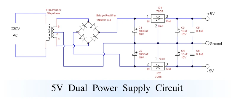
1. 5 Volt Dual Supply Circuit Diagram
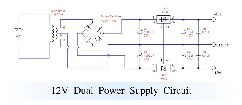
2. 12 Volt Dual Power Supply Circuit Diagram
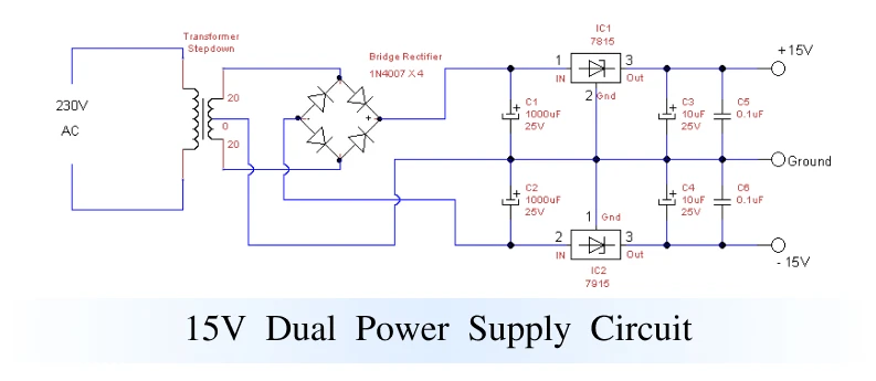
3. 15 Volt Dual Supply Circuit Diagram
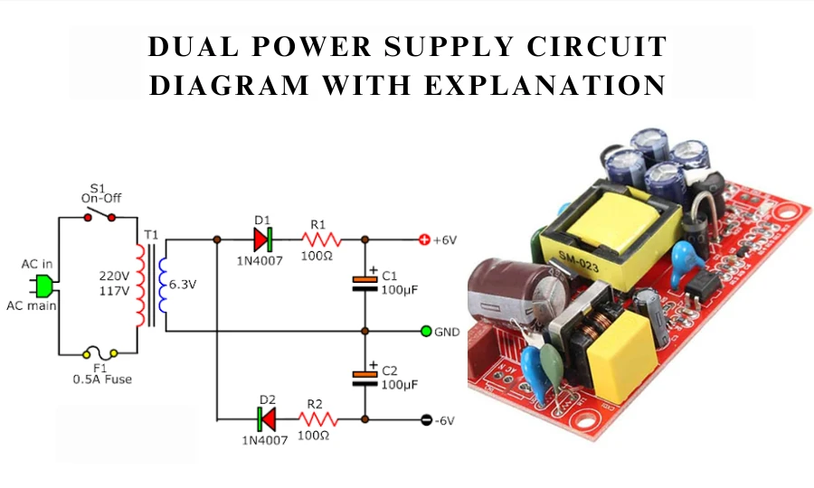
Dual Power Supply Circuit Diagram
Below is a simple dual power supply circuit diagram using 7812 and 7912 voltage regulators.
Required components:
- Transformer (12V-0-12V) – Converts high AC voltage to lower AC voltage
- Bridge rectifier (4 diodes - 1N4007 or equivalent) – Converts AC to DC
- Capacitors (4700µF, 1000µF, 10µF) – Filters and smooths the voltage
- Voltage regulators (7812 and 7912) – Provides stable +12V and -12V
- Resistors (optional to limit current)
How this circuit works:
- The transformer steps down the high AC voltage from the main power source.
- The bridge rectifier converts AC voltage to DC voltage.
- Capacitors smooth the voltage by removing ripple.
- The 7812 regulator ensures a stable +12V output, while the 7912 regulator provides a stable -12V output.
- The final output provides three connections: +12V, -12V, and 0V (ground), which can be used for electronic circuits.
Why do we need a dual power supply?
Many electronic devices require both positive and negative voltages for proper operation. Dual power supplies help in the following ways:
- Ensures stable voltage for circuits that require balanced power.
- Prevents signal distortion in amplifiers and op-amps.
- Provides stable DC power to sensitive devices.
- Works well for both analog and digital circuits.
For example, an operational amplifier (op-amp) requires +12V and -12V to function properly. Without a dual power supply, the op-amp may not function properly or may even be damaged.
Uses of Dual Power Supplies
Dual power supply circuits are used in:
- Operational amplifier (op-amp) - Used in signal processing and analog circuits.
- Audio amplifier - Provides a stable voltage for better sound output.
- Microcontroller circuits - Used in embedded systems that require dual power.
- Communication devices - Essential for RF and networking applications.
- Medical devices - Used in sensitive electronic devices.
Benefits of dual power supplies
- Provides both positive and negative voltages.
- Ensures stable power output for complex circuits.
- Reduces interference in sensitive electronic circuits.
- Improves efficiency in high-performance applications.
Conclusion
A dual power supply is an important circuit for electronic devices that require both positive and negative voltages. The dual power supply circuit diagram with an explanation shows how we can use transformers, rectifiers, capacitors, and voltage regulators to create a reliable power source.
By understanding how a dual power supply works, we can easily build and use it in amplifiers, op-amps, and microcontroller circuits. If you are working on a project that requires a stable and reliable


Sign in to leave a comment.