Designing audio visual systems often begins with quick sketches. Many AV professionals and integrators like to map out ideas on paper during meetings or site visits. These hand-drawn sketches can be useful for brainstorming, but they are not ideal for sharing with teams, clients, or installers. A clean and professional diagram is essential for accurate documentation and smooth implementation. This is where Signal Flow Diagram Software comes in. In this blog, we will guide you through the process of converting hand-drawn signal flow sketches into polished digital diagrams.
Why Convert Hand-Drawn Sketches to Digital Diagrams
While a hand-drawn sketch is useful for capturing ideas in the moment, it has limitations. Paper sketches can be hard to read, especially if they are messy or contain unclear labels. They are also difficult to update or modify as the project evolves. A digital diagram solves these problems by providing a clean, organized, and editable version of your design. Using Signal Flow Diagram Software also allows you to export, share, and archive your diagrams easily. This ensures that everyone on the team is working from the same plan.
Step 1: Choose the Right Signal Flow Diagram Software
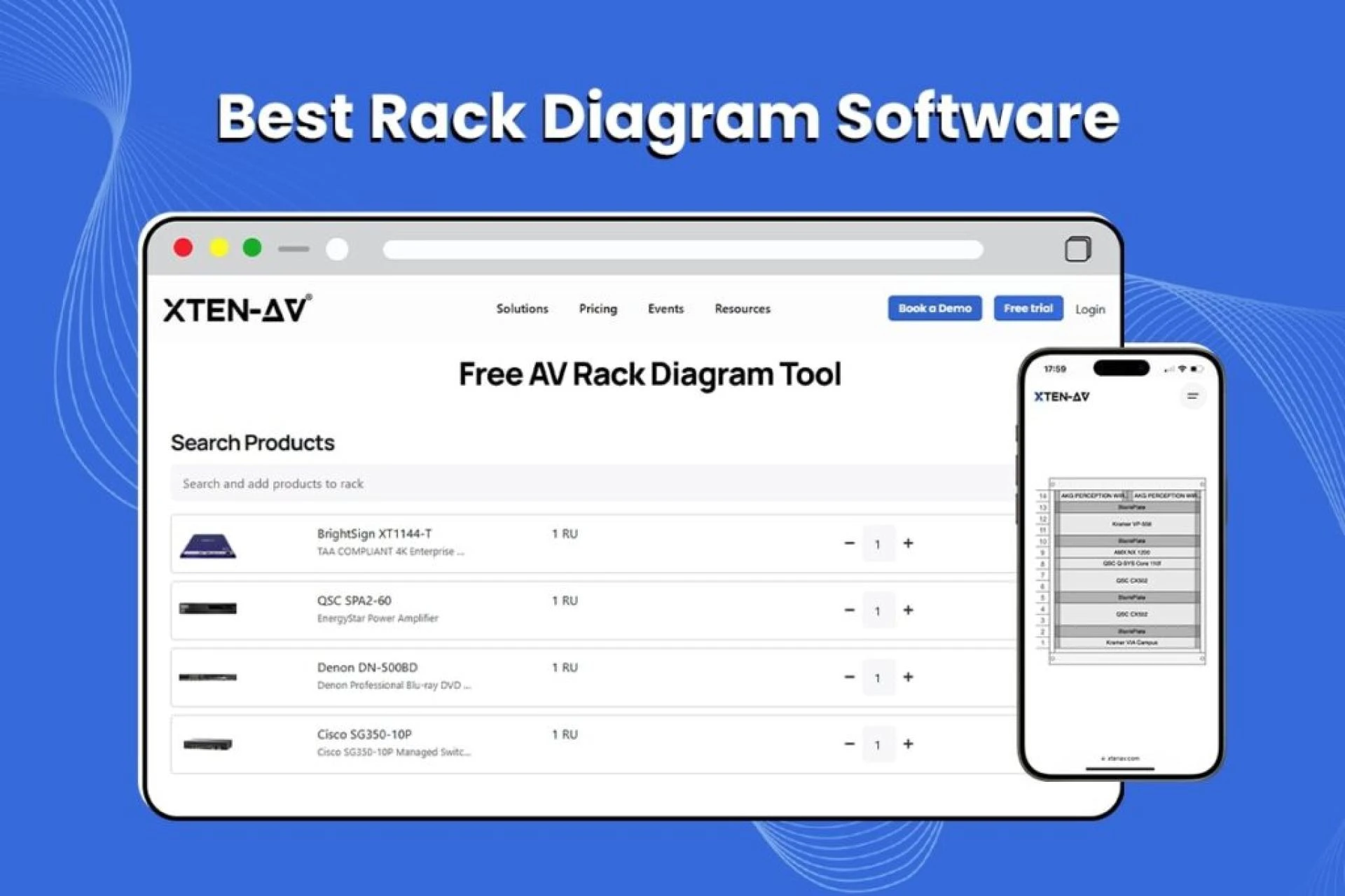
Before you start converting your sketch, select a software tool that meets your needs. Some popular options include XTEN-AV, Visio, Draw.io, and Lucidchart. XTEN-AV is a great choice for AV professionals because it is purpose-built for audio visual system design. It offers a library of AV symbols, AI powered features, and automated documentation tools. Other tools like Draw.io and Lucidchart are good for general diagramming and offer free versions. Choose software that fits your project size, team workflow, and budget.
Step 2: Scan or Photograph Your Sketch
To begin the conversion process, you need a digital copy of your hand-drawn sketch. Use a scanner or take a clear photograph with your phone. Make sure the image is well lit and free from shadows or glare. Save the file in a common format such as JPG or PNG. This image will serve as your reference as you create the digital version.
Step 3: Upload or Display the Sketch as a Reference
Some Signal Flow Diagram Software allows you to import an image onto your design canvas. If your software supports this, upload your scanned sketch and place it on a background layer. This will help you trace or align your digital components to match the original layout. If your tool does not support image import, simply keep the image open on a second screen or print it out for reference as you work.
Step 4: Add Devices and Components
Now start adding your devices to the digital diagram. In XTEN-AV or similar software, you can drag components from the symbol library onto your canvas. Place microphones, mixers, processors, amplifiers, and speakers according to your sketch. Arrange them in a logical flow, typically with sources on the left, processing devices in the middle, and outputs on the right. Take this opportunity to clean up the layout if needed. Digital diagrams allow you to align, group, and space elements neatly.
Step 5: Draw Connections
Once your devices are in place, begin connecting them using the software’s drawing tools. Click on a port or device and drag a line to the next device in the signal path. Label each connection with the type of signal it carries such as XLR, HDMI, or CAT6. One of the advantages of using Signal Flow Diagram Software is that it helps you ensure connections are clear and consistent. In XTEN-AV, you can also use automated connection features to speed up this process.
Step 6: Add Labels and Notes
Your original sketch may have included handwritten labels or notes. In the digital diagram, add these using text tools. Label all devices clearly with their names or model numbers. Add notes where necessary to explain signal routing choices, special configurations, or installation instructions. Well-labeled diagrams reduce confusion and make the system easier to install and maintain.
Step 7: Review and Optimize
Once you have recreated your sketch in digital form, review the diagram carefully. Look for any missing connections, unlabeled components, or unclear signal paths. Most Signal Flow Diagram Software includes tools for aligning objects, checking spacing, and organizing layers. Take advantage of these to produce a clean and professional looking diagram. If you are using XTEN-AV, you can also run AI powered checks to identify potential issues or suggest optimizations.
Step 8: Export and Share
When your digital diagram is complete, export it in a format suitable for sharing. Common export formats include PDF, PNG, and SVG. You can print the diagram for use on site or share it digitally with team members, clients, or contractors. If your software is cloud-based, such as XTEN-AV or Lucidchart, you can also provide access to the file directly so others can view or comment in real time.
Step 9: Keep Your Diagram Updated
One of the best advantages of converting your sketch into a digital diagram is that it is easy to update as your project evolves. If equipment selections change, room layouts are adjusted, or signal paths are modified, you can quickly make edits in your diagram. This keeps your documentation accurate and helps ensure a smooth installation and future maintenance.
Tips for a Smooth Conversion
Here are a few extra tips to help you convert hand-drawn sketches into polished digital diagrams.
- Plan for clarity. Take advantage of the digital format to clean up messy areas of your original sketch. Arrange devices and connections neatly.
- Use layers or groups. Many Signal Flow Diagram Software tools support layers or grouping. Use these features to separate elements like audio, video, and control signals.
- Save versions. As you update your diagram, save versions at key milestones. This gives you a record of changes and makes it easy to revert if needed.
- Collaborate early. Share drafts of your diagram with your team as you work. Their feedback can help catch mistakes or suggest improvements.
Conclusion
Converting a hand-drawn signal flow sketch into a digital diagram is an important step in professional AV system design. With the help of Signal Flow Diagram Software, you can create clear, accurate, and shareable documentation that supports your project from design to installation. By following these steps, you can turn rough sketches into polished diagrams that help your team deliver great results. Whether you are using XTEN-AV or another tool, the key is to use software that makes your workflow faster, easier, and more reliable.
Read more: https://repurtech.com/best-signal-flow-diagram-software-for-conference-room-av-projects/


Sign in to leave a comment.